On September 3rd OpenAI launched GPT-6 Astra, and one of the launch demos was fifteen seconds of the model doing PCB layout in KiCad: placing parts, routing copper, “turning an electronic schematic into a manufacturable PCB.” Within a week my feed was wall to wall circuit boards, from flight controllers to a star tracker the model ordered from JLCPCB itself, and the name everyone settled on was vibe hardware.
GPT-6 Astra doing PCB layout in KiCad 🤯🤯
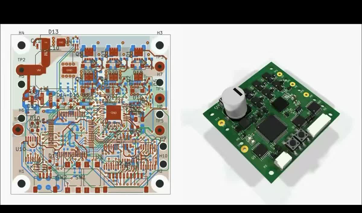
965K views · Sep 3, 2026 · open on X ↗
I design production hardware at a big company, and I use AI to do it every working day, so I have an opinion on all this. It isn't the one the feed suggests. The demos point the model at the one part of the job it's worst at, and the real gains are hiding in the less photogenic work around the board.
- 1.Harness and context decide almost everything. Everyone gets the same model. What you hand it is yours.
- 2.Keep it close to text. KiCad over binary formats, CLIs over MCP, a CLAUDE.md that reads like a header file, and never a raw datasheet PDF.
- 3.It's superb at translation. Flex pinouts, Gerber diffs, DFM triage: anything that moves information between tools that never talked.
- 4.It's bad at layout. On real industrial boards the best model routes 12.6% of nets cleanly. Humans route 93.6%.
- 5.Half of “taste” is physics nobody grades. EE needs a layout benchmark with field solvers in the loop.
- who
- a systems EE at a big hardware company, ex Tesla, using an agent every working day
- covers
- schematic, layout, and the work around them
- skips
- firmware, which has been covered to death
- tools
- Claude Code, KiCad at home, my employer's tools at work
- shelf life
- written October 2026. parts will be wrong by Christmas
## 1. Know what your model is good at
Two terms do most of the work in this post:
- ▸Harness: everything wrapped around the model. The tools it can call, the files it can read, the instructions it starts with, the loop it runs in.
- ▸Context: what's in front of it when it answers. Which schematic, which datasheet, which slice of the system. (Tobi Lütke and Andrej Karpathy made “context engineering” the name for this last year.)
Everyone gets the same model, more or less on the same day. The harness and the context are yours, though, and in my experience they account for nearly all of the difference between a result that saves you an afternoon and one that sends you back to the datasheet angry.
The best thing I've read on this is Claude-shaped science, by Matthew Schwartz, a Harvard physicist who spent months trying to get Claude to do physics the way he does physics. It didn't work, and the interesting part of the essay is what he did next:
> Instead of treating Claude like the collaborator I wanted it to be, I started to treat it like the collaborator it actually is.
He went looking for the problems that suited it, built a harness called BootLoops to steer it toward them, and came out the other side with thirty-six manuscripts. That is the whole skill in electrical engineering too. A model in 2026 is superhuman at some parts of board design and worse than an intern at others, and the job is knowing where that line sits and keeping the model on the right side of it. The catch is that the line moves every few months, so whatever you learn about it has a short shelf life.
## 2. Harness: get the model close to the files
Models are best at text. Every other format is a translation layer, and every translation costs you some accuracy and a lot of tokens. Three rules fall out of that, and they're the ones I'd give anyone setting up a harness for hardware work:
| rule | why | evidence |
|---|---|---|
| Store designs as text | The agent reads the schematic, netlist, and board directly, and can patch the tool itself. | KiCad; i2cjak's Backplane shows every agent edit to a board live |
| Prefer CLIs to MCP | Every MCP server loads its tool definitions into context on every turn. | Playwright MCP: 13.7k tokens before you've done anything. MCP costs 4–32× more tokens |
| Write CLAUDE.md like a header file | Declarations stay in context; definitions stay on disk until something calls them. | Anthropic's progressive disclosure; HumanLayer's “prefer pointers to copies” |
If I were starting a hardware company tomorrow, I wouldn't pick an ECAD tool that stores designs as binaries, because every binary file is a wall between the model and your design. The honest counterexample is Eli Hughes, who wrote open-source parsers to crack Altium files open and feed the netlists to Claude and Codex for design reviews. So binary isn't a dead end. Someone just has to build the bridge before the model can cross it, and with KiCad the bridge is already there.
At the other extreme is atopile, which describes the whole circuit as code. When I was at Tesla there was a real push to use it, because we wanted to move as fast as humanly possible, and I understood the appeal. My problem with it was, and still is, that there's no schematic: you read code to find out how a buffer is hooked up. Models love that. Electronics engineers want a schematic, and I don't think that changes because the machine would prefer otherwise.
On CLIs: at work, a lot of my harness is small command-line tools the agent wrote for our internal web tools, things like the parts database, the issue tracker, and the place suppliers post their DFM comments. I describe what I want out of the tool, the agent builds the command, and I've stopped caring much how they work inside. Anthropic's own docs back the approach: “CLI tools are the most context-efficient way to interact with external services.”
And here's the header file. In embedded C, a header declares what exists and where it lives, and the definitions only get pulled in when something calls them. A CLAUDE.md should work the same way, and mine looks roughly like this:
One gotcha worth knowing: Claude Code's @path import loads the whole file at launch, which makes it an #include, not a pointer. A plain sentence saying where the file lives, and when to open it, does the job better and costs one line.
## 3. Context: the model is an expert in a box
The mistake I see most often, and I see it from good engineers, goes like this: paste a circuit question into a chat window, get a wrong answer, and decide the model is dumb.
Try this instead. You're a very good EE, and someone locks you in a box, slides a schematic you've never seen under the door, and asks whether the current-sense amp is hooked up right. There's no datasheet and no system diagram, and you have no idea what the board plugs into. You'd guess, you'd mostly be right because you're good, and some fraction of the time you'd be confidently wrong. That's the model, every time you ask it something cold. Anthropic's prompting guide has a politer version, “a brilliant but new employee who lacks context,” but the box is closer to how it looks from the model's side of the door.
I did exactly this to myself this week. I was designing a current-sense amplifier circuit and hadn't put the part's datasheet in my knowledge base yet, and the model told me, with total confidence, that the ground pin could go to a negative rail. It can't. The model didn't get any smarter between that answer and the right one; the only thing that changed was the datasheet.
So what does “context” actually mean for a board? In my experience it's four things, roughly in order of how often people forget them:
- ▸Every datasheet on the sheet, as text. More on that below.
- ▸The system around the board. Every connector, harness, and module on the other end. At Tesla I could export that from an in-house tool. Most places, it lives in your systems engineer's head, so go get it.
- ▸History. Past issues, design rules, the last three revisions.
- ▸An index on top, so it only opens what it needs. I use a version of Karpathy's LLM wiki. It works; it's also a chore to keep current.
My biggest pet peeve is the raw datasheet PDF dropped into a chat with “design me a circuit around this.” It feels like you've handed the model everything it needs, which is exactly what makes it a trap. Three things go wrong:
- ▸It isn't really text. A PDF stores instructions for drawing glyphs. Reading order and tables have to be reconstructed (LlamaIndex explains why).
- ▸It's expensive. Claude sees each page as an image plus text, 1,500 to 3,000 tokens a page. One datasheet can eat your context before you've asked anything.
- ▸Agents grep it. The ones that shell out to a text extractor are searching a document that was never meant to be searched.
So I pre-digest every datasheet before the model ever sees it. Baidu's Unlimited-OCR runs locally on my laptop through MLX and handles the bulk of the text for free, and anything it isn't confident about goes to Claude, which is slower and costs money but can actually read a table. Ari Mahpour at Altium built something similar, which made me feel a little less crazy for doing it.
None of this should be necessary forever. Datasheets are written for people, their main reader is quickly becoming a model, and somebody is going to fix the format. Here's where the vendors stand as of this fall:
| who | what exists |
|---|---|
| Microchip | a free, public MCP server for its catalog |
| TI | a JSON product API, approved customers only |
| ST, Infineon, Renesas | no official server as of August |
| datasheets.md | a startup re-extracting the PDFs |
| a standard | none for a whole datasheet, graphs and all |
I'd bet heavily on that last row changing within a couple of years. Machine-readable datasheets were the backup idea on my YC application, and I still think every agent that touches hardware is going to need them.
## 4. What it's actually good at: translation
With the harness and the context in place, the thing that surprised me most isn't any single task. It's that the model is a universal adapter. Hardware engineering is full of files that were never designed to talk to each other (the schematic, the board, the mechanical model, the flex outline, the supplier's DFM report), and a big part of my day used to be carrying information between them by hand. The model can carry it, and it doesn't get bored.
The best example is a test flex I designed recently. One of our boards has a 36-signal board-to-board connector, and we wanted every signal broken out to 2.54 mm headers so we could probe them on the bench. The complication was that the reference flex has a bend and this one had to come out straight, so the pinout couldn't just be copied across. I gave the agent the reference pinout and the four-layer FCCL stackup and let it go.
It assigned every net, planned the fanout, drew the outline in Matplotlib, and exported it as IDX for the mechanical side. (Drawing a board outline turns out to be the same problem as drawing an SVG, which these models are extremely good at.) I checked every pin by hand afterwards and changed nothing. It isn't fabbed yet, so the bench gets the last word, but an afternoon of careful, boring work became one prompt and a review.
| from | to | what it catches |
|---|---|---|
| reference flex pinout | new flex breakout + IDX outline | an afternoon of manual pin mapping |
| board → flex → connector → board | interconnect table, checked in 3D | mirrored footprints, flips through a bend, pin 1 landing on pin 36 |
| Gerber rev A + rev B | an overlay diff | what actually moved, without flicking between windows |
| the layout | a picture for the mechanical engineer | everything grayed out except the one thing they need |
| supplier DFM comments | a triage list against our guidelines | which comments are real. most aren't |
| schematic | an Excel quick-start calculator | the design math, in a format every engineer can poke at |
The honest gap is simulation. Even with text netlists, I haven't had good results getting it to build and run LTspice models, though I also haven't put real harness work into that, so some of the blame is mine. Everything else I use it for is below, sorted by where it sits in the job. Steal whatever's useful.
▸Everything I use it for23 uses across office work, parts, schematic, layout, and manufacturing, each ratedexpandcollapse
## 5. It can rotate a shape. It can't route a board.
Which brings us back to the feed. The thing everyone is excited about is layout, and layout is exactly where the models are weakest.
I used to say LLMs aren't shape rotators, and it turns out that's too blunt. They've gotten very good at flat, discrete spatial problems, the kind of puzzle you can write down as a grid. What they still can't do is continuous geometry in three dimensions, or hundreds of interacting constraints spread over a large area at once, and that happens to be a pretty good description of a circuit board.
The board-specific numbers are worse. OmniRouting took 1,681 real industrial boards, each with a placement that engineers had already proven routable, and asked models to finish the job:
| who routed it | nets clean |
|---|---|
| human engineers | 93.6% |
| a classic algorithmic router (PcbRouter) | 56.2% |
| best model, with every tool | 28.0% |
| best model, on its own | 12.6% |
PCBWorld found the same shape: a GPT-5.4 agent cleanly routed 65% of small real boards and none of the medium ones. A tiny RL policy trained only against a DRC checker beat it on both. That last part matters, and I'll come back to it: the small model won because something was grading it.
As far as I can tell there are two reasons, one about how the model sees the board and one about how it remembers it:
- ▸It can't see the copper. Images arrive as 28-pixel patches. The arithmetic is below.
- ▸It has no picture to update. The board exists to the model as a list of coordinates, and nothing redraws a mental map when one moves. The Spatial Competence Benchmark calls the result “locally plausible geometry that breaks global constraints.” Every segment looks fine. The board is shorted.
| step | value |
|---|---|
| the image | a 100 mm board, shown edge to edge at 2576 px |
| one patch | 28 × 28 px (Claude's vision docs) |
| so one token covers | about 1.1 × 1.1 mm of board |
| inside that square | a 0.1 mm trace, its clearance, and a whole 0.4 mm-pitch BGA ball |
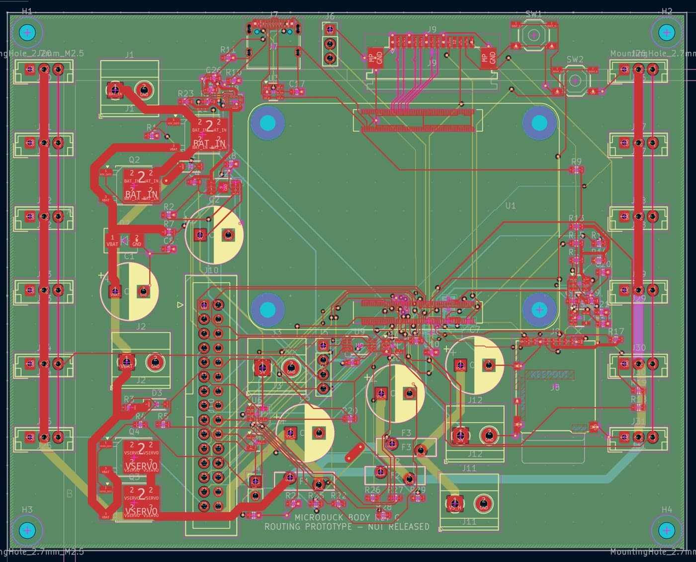
The board everyone piled on was Microduck, a four-layer robot board that Astra “one-shotted.” Here's the layout from the original post, so you can play spot-the-problem before reading the replies:
| who | what they called out | about |
|---|---|---|
| i2cjak | connectors you can't physically reach; watch the model "like a hawk" so it doesn't paint itself into a corner | Microduck |
| BlindVia | screw terminals blocked so you can't get a wire in | Microduck |
| Luke Weston | the USB-C connector, the FFC connector, and signal integrity on the camera diff pairs | Microduck |
| DeepPCB | 9 of 32 vias in pads, five track widths under one empty net class, a split power plane | Microduck |
| Michael W. | USB D+/D- routed terribly, a GPIO expander added to dodge routing, "the most awful buck converter layout I have ever seen" | his own AI-routed board |
| kelin | a Shenzhen PM whose new clients are software engineers with vibe-designed boards that don't work | the fab's view |
That's only what shows up in a screenshot, too. Most of these boards would probably work on a bench, which is all a demo needs. Start thinking about ESD, EMC, SI and PI, or about building ten thousand of them, and they fall apart. The buck converters are the worst offenders: sprawling hot loops, giant switch nodes, and inductors on the far side of the board from the IC. I'm surprised some of them turn on.
What I'd do instead is let the model drive the tool that was actually built for geometry, and keep it on the parts of the job it's good at:
- 1.The model reads the stackup, the datasheets, and the fab's capability sheet.
- 2.It writes the net classes, widths, clearances, and layer rules. Nobody likes doing this, which is why autorouters get a bad name.
- 3.The autorouter does the geometry. Given good constraints it will escape a BGA with dogbones on the layers you pick (there's an old EEVblog video on exactly this).
- 4.The model checks DRC and diffs the result; a human routes or reviews the critical nets.
JLCPCB's review of an Astra board suggests the model already does a version of this: it hand-routed the power and switching nets and gave the rest to Freerouting. I haven't run this loop end to end myself yet, and it's the next thing I want to try.
## 6. Taste is scar tissue
The usual answer to all of this is that the models lack taste. I think that's half right, so let me start with the half that is.
Taste comes from doing it wrong once. A board fails EMC, and you go to the chamber, and you spend days learning about component orientation, loop area, and the geometry of fields until you find the thing. After that you look for that extreme on every board you see. A fab explains what an unbalanced stackup does in reflow, and from then on you can glance at a layout and tell whether the designer was thinking about how much copper the acid would take off each layer. None of it came from school.
Here's the same board laid out both ways, with the six places I look in the first thirty seconds. Flip the toggle and watch the same six spots change.
| 1 | ESD at the connector | The TVS diode (D1) sits on the USB lines right at the connector, so a zap is clamped before it goes anywhere. |
| 2 | Buck input loop | Input cap tight against U2. The hot loop (amber) is tiny. |
| 3 | Switch node | Inductor right next to the switch pin. The switch node is a small copper island. |
| 4 | Placement | Decoupling caps hug every side of U1, and the passives sit in rows with one orientation. Someone thought about pick-and-place and rework. |
| 5 | Ground return | Solid ground under the USB pair. The return current (cyan) runs straight back underneath it. |
| 6 | Copper balance | Each layer roughly matches its mirror in the stackup (L1↔L4, L2↔L3). It etches evenly and stays flat in reflow. |
A newbie can look at a board from a top-tier company and see that it's good, but can't tell you why. The model is in the opposite position. It has the words: the loop-area rules, the EMC textbooks, and every app note on buck layout ever written are almost certainly in the weights. What it doesn't have is the analogies, the reflex that says this looks like the board that failed in the chamber last spring. It designs from first principles every time, because it's still in the box.
## 7. Half of taste is physics nobody grades
Now the half I don't buy. Look at those six callouts again, and notice that most of them aren't really taste at all. They're physics with a number attached:
| the glance | the physics | what measures it |
|---|---|---|
| ① ESD placement | inductance of the clamp path | partly rules, partly extraction |
| ② buck input loop | hot-loop inductance | parasitic extraction |
| ③ switch node size | radiating copper area at the switching edge | EM solver |
| ④ decoupling placement | PDN impedance vs frequency | PDN analysis |
| ⑤ slot in the ground | return-path discontinuity | SI field solve |
| ⑥ copper balance | copper area ratio per layer | a twenty-line script |
Models get good at whatever can be checked automatically, which is why they got good at code first: you can run the tests, and the tests don't care how confident the model sounded. So it's worth asking what actually gets checked in EE today:
| check | graded by | open, headless tool that could grade it |
|---|---|---|
| every net connected | OmniRouting, PCBWorld, every demo | kicad-cli |
| DRC / ERC clean | OmniRouting, PCBWorld, every demo | kicad-cli |
| circuit works in SPICE at tolerance corners | EEBench (schematic only) | ngspice |
| copper balance per layer | nobody | kicad-cli exports + a script |
| PDN impedance, DC IR drop | nobody | Elmer, ngspice |
| impedance, crosstalk, return paths | nobody | openEMS, gerber2ems |
| radiated emissions | nobody | openEMS (slow) |
| works at ten thousand units | nobody | none. only reality grades this |
EEBench, from the atopile team, is the best EE benchmark there is: real parts, ngspice at tolerance corners, BOM cost, no LLM judge. Claude Opus 5.5 leads at 75%. But its methodology puts layout out of scope, and the routing benchmarks only check connectivity and DRC.
I couldn't find a single published example of a language model laying out a board against a PDN or field-solver reward. Which means the Astra demo was optimized for exactly what it showed, a board that connects, because that's the only thing anyone is grading. Remember the PCBWorld result: the small model beat the big one because something was checking its work.
I can't see the labs building this on their own. Field solvers are slow, the good commercial ones are license-gated, and EE is a small market next to code. The models would also need to get much better at physics before the scores meant anything: HWE-Bench, which asks for board-level schematics from scratch and checks them in simulation, tops out at 8%.
So here's my ask. Look at the right-hand column of that table: every “nobody” row already has an open-source tool that runs headless. Someone should wire them into one benchmark that scores a layout on copper balance, PDN impedance, IR drop, and return paths, on top of DRC. atopile already showed that if you build the environment, labs will train on it.
Build the one that measures the part we actually ship. If you're building it, I'd like to help.
## Two boxes
Here's where I land, for now. Vibe hardware is real, and it's going to be huge, mostly for people next to electrical engineering: firmware, software, and mechanical engineers who need a bench tool and no longer have to ask someone like me for one. That's great. The serious end will look more like software did. Anyone can build an app now, but very few people can run a platform for millions of users, and the ones who do use AI to go faster, not to go away.
Maybe I'm biased; I've spent my whole adult life getting good at this. But the difference from software is the verify loop. Code fails in seconds. A board fails in the chamber, six weeks after you sent it out. Until that loop is something a model can run, it will keep learning the parts of the job that can be checked, and those aren't the hard ones.
There are two boxes in this post. The first is the one we put the model in every time we ask it something cold, and that one's easy to open: hand it the datasheet, the system, the pointers. The second is the one it was trained in, where the only thing anyone grades is whether the board connects. That box has to be opened from the outside, with a field solver. Until someone does, I'll keep doing the layout, and let it do everything else.
▸ cat sources.md · every link in this post · click to expand
- Claude-shaped science, Matthew Schwartz (Anthropic, Oct 2026) ↗
- BootLoops ↗
- Harness design for long-running application development (Anthropic) ↗
- Effective context engineering for AI agents (Anthropic) ↗
- Tobi Lütke on "context engineering" ↗
- Andrej Karpathy on "context engineering" ↗
- Claude Code best practices ↗
- Claude Code memory and @imports ↗
- Agent Skills and progressive disclosure (Anthropic) ↗
- Writing a good CLAUDE.md (HumanLayer) ↗
- Code execution with MCP (Anthropic) ↗
- What if you don't need MCP at all? (Mario Zechner) ↗
- MCP vs CLI benchmark (Scalekit) ↗
- Prompting best practices (Anthropic) ↗
- LLM Wiki (Karpathy) ↗